Luận án Phân tích tính ổn định kết cấu dầm bơm hơi vật liệu composite
Trang 1
Trang 2
Trang 3
Trang 4
Trang 5
Trang 6
Trang 7
Trang 8
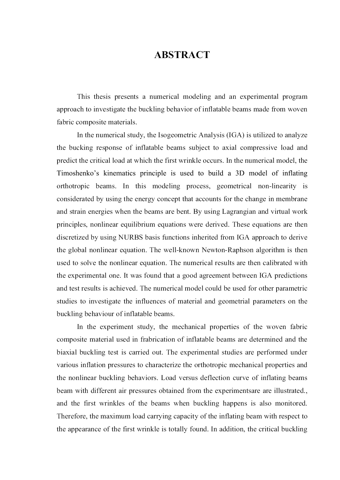
Trang 9
Trang 10
Tải về để xem bản đầy đủ
Bạn đang xem 10 trang mẫu của tài liệu "Luận án Phân tích tính ổn định kết cấu dầm bơm hơi vật liệu composite", để tải tài liệu gốc về máy hãy click vào nút Download ở trên.
Tóm tắt nội dung tài liệu: Luận án Phân tích tính ổn định kết cấu dầm bơm hơi vật liệu composite
uadrature for NURBS elements has been investigated and proven as reliable in the literature Chawla [1] and Wolfgang [25] as well as in the benchmark examples in this thesis (for the examples presented in this thesis, Gauss integration has been used). An efficient quadrature for NURBS-based isogeometric analysis that makes use of the higher continuities between elements, and therefore is more efficient than Gauss quadrature, is developed by Hughes [40]. Equivalent to finite elements, a NURBS element is defined by a set of nodes and corresponding basis functions. The nodes are the NURBS control points which carry the degrees of freedom for the analysis and boundary conditions are applied to them. Since the element formulation in this thesis is displacement-based, the degrees of freedom are the displacements of the control points. For two-dimensional structures this means that every control point has three degrees of freedom, namely the displacements in x- and y- direction. It is important to note that with this definition 3.1 Overview and basics of Isogeometric Analysis 47 of elements, the basis functions are not confined to one element but extend over a series of elements, as illustrated in Figure 3.11. This is a very important difference to classical finite elements because it allows higher continuities of shape functions over the element boundaries. As in the p-version of the finite elementingmethod Pilkey [41], the high-order nature of the basis functions generally results in higher accuracy compared to low- order elements. In contrast to p-version elements, NURBS-elements also have high- order continuities between elements, which is the basis for the element formulation presented in the next chapter. On the other hand, it means that the elements are interconnected and not independent of each other. The basis functions inside a knot span are defined by the Cox-deBoor recursion formula and depend on the neighboring knot spans, see Eq. 3.4. Therefore, it is not possible to define a single NURBS element without a complete NURBS patch. In this context, it is worth discussing the term elements since they are not independent, elementary parts that can be assembled arbitrarily to form a bigger model. In the implementation persepctive, these elements can be treated exactly in the same way as classical finite elements. The stiffness matrix, for example, is evaluated on element level and assembled to the global stiffness matrix. The only difference is the use of different shape functions. The fact that the corresponding nodes, i.e. control points, usually lie outside the element, is solely a consequence of the used basis functions and does not make any difference in the treatment of these elements in a finite element code. Many locking phenomena in structural analysis are a consequence of the low-order basis functions that cannot correctly represent the physical behavior Bezier [42] and Hughes [23]. Since NURBS are higher order functions, these locking effects can be avoided efficiently. The following important properties of NURBS as basis for analysis are summarized: • The basis functions fulfill the requirements of linear independence and partition of unity. They have a local support, depending on the polynomial degree. • Basis functions have higher-order continuities over element boundaries. CHAPTER 3: THEORETICAL FORMULATIONS 48 • Degrees of freedom are defined on the control points. • The isoparametric concept is used. • Rigid body motions are treated correctly (zero strains) due to the affine covariance property of NURBS. • Locking effects stemming from low-order basis functions can be precluded efficiently. 3.1.10 Isogeometric Analysis versus Classical Finite elementingAnalysis The use of NURBS basis for geometric modelling and analysis is the significant difference of isogeometric analysis versus standard finite elementingmethod. Isogeometric analysis employs NURBS basis functions to construct exact geometry at all levels of discretization, while the classical families of interpolatory polynomial as Lagrange polynomials or Hermite polynomials are widely utilized in typical finite elementinganalysis. Major differences are listed in Table 3.1. On the other hand, isogeometric analysis and classical finite elementingshare many common features. For instance, they are both isoparametric implementations of Galerkins method, accordingly, isogeometric analysis inherites the computing implementation of finite elementingprocedure. Others are given in Table 3.2. Table 3.1 NURBS based isogeometric analysis versus classical finite element analysis. (Wolfgang [25]) Isogeometric analysis Classical finite elementing analysis - Exact geometry - Approximate geometry - Control points - Nodal points - Control variables - Nodal variables - Basis does not interpolate control points and variables - Basis interpolates nodal points and variables - NURBS basis - Polynomial basis 3.2 Cotinuum-based governign equations of stability problems of inlfating beams 49 - High, easily controlled continuity - 0C -continuity, always fixed - hpk-refinement space - hp-refinement space - Pointwise positive basis - Basis not necessarily positive - Convex hull property - No convex hull property - Variation diminishing in the presence of discontinuous data - Oscillatory in the presence of discontinuous data Table 3.2 Common features shared by isogeometric analysis and classical finite element analysis. (Wolfgang [25]) Isoparametric concept Galerkins method Code architecture Compactly supported basis Bandwidth of matrix Partition of unity Affine covariance Patch tests are satisfied 3.2 Cotinuum-based governign equations of stability problems of inlfating beams A large number of analytical analyses related to the inflating beams and arches are available in literature, concerning both theoretical and experimental analysis. One important aspect is need to build the best adapted analytical modeling for beam structures. Euler-Bernoulli kinematics and the Timoshenko kinematics are widely used to gain the analytical solutions and to develop the formulations for inflating beams made of woven fabrics. Comer [3] derived a load deflection theory in the case of isotropic beams. Main [43] and Main [5] proposed a method for analyzing the inflating fabric beams with a model analogous to the shear-moment method and developed the theory considering orthotropic membrane model. Fichter [7] Analytical buckling analysisconstructed Timoshenko cylindrical inflating beams CHAPTER 3: THEORETICAL FORMULATIONS 50 made of elastic isotropic textile fabric based on energy minimization approach. Effects of air pressures to the load carrying capacity of the beam were taken into account. In general, the beam theoretical model is developed based on the Assumptions are made as follows: (i) the cross section of the inflating beam remains undeformed under applied load, (ii) the cross section translation and rotations are small, (iii) the circumferential strain is negligible. Wielgosz [10] presented analytical solutions for inflating plates and tubes based on Timoshenko kinematics. The work took into account the geometric stiffness and the residual force effect due to the internal pressure. They indicated that the limit load is proportional to the applied pressure and that deflections are inversely proportional to the material properties of the fabrics and to the applied pressures. In order to improve Fichter’s theory, Wielgosz [44] proposed a new formulation using the virtual work principle in Lagrangian form and Kirchhoff hypothesis with finite displacement and rotation to derive nonlinear equations of inflating beams. Davids [17] and Davids [18] presented nonlinear load-deflection response of Timoshenko inflating beams. Parametric studies have been also investigated in their work. Malm [19] used 3D isotropic fabric membrane finite element model to predict the beam load-deformation response. In this chapter, theoretical formualtions developed by Nguyen and his coleagues ([22], [52] and [130]) are employed for the buckling problems of inflating composite beams is presented. The obtained governing equations are then discretized in accordance to IGA manner in the next chapter to find the numerical solutions of the buckling problems. It is noted that in the previous work of Nguyen ([22] and [52]), the author used traditional finite element approach to solve the problem. 3.2.1 Mathematical description of inflating beams In this study, we focused our work on the Timoshenko beams made from orthotropic material. For inflating structures, the load is applied in two stages: First, the beam is inflating to the pressure p, and other external forces are applied. At the beginning of the first step, the internal pressure is zero and the beam is in its natural state Figure 3.13a. The reference configuration corresponds to the end of the first 3.2 Cotinuum-based governign equations of stability problems of inlfating beams 51 stage Figure 3.13b. The Green-Lagrange strain measure is used due to the geometrical nonlinearities. Figure 3.13 HOWF inflating beam: (a) in natural state and (b) in the reference configuration (inflating state) Figure 3.13 shows an inflating cylindrical beam made of an HOWF. 0 0 0 0, , ,l R t A and 0I represent respectively the length, the external radius, the fabric thickness, the cross-section and the second moment of inertia around the principal axes of inertia Y and Z of the beam in the reference configuration which is the inflating configuration. 0A and 0I are given by 0 0 02A R t = 3.22 2 0 0 0 2 A R I = 3.23 where the reference dimensions 0 0,l R and 0t depend on the inflation pressure and the mechanical properties of the fabric Apedo [45]: ( )0 1 2 2 lt t pR l l l v E t = + − 3.24 CHAPTER 3: THEORETICAL FORMULATIONS 52 ( ) 2 0 2 2 lt t pR R R v E t = + − 3.25 0 3 2 lt t pR t t v E = + 3.26 in which ,l R and t are respectively the length, the fabric thickness, and the external radius of the beam in the natural state. The internal pressure p is assumed to remain constant, which simplifies the analysis and is consistent with the experimental observations and the prior studies on inflating fabric beams and arches. The initial pressurization takes place prior to the application of concentrated and distributed external loads, and is not included in the structural analysis per se. The slenderness ratio is s L = where 0L l= is the beam length and 0 0 I A = is the beam radius of gyration. The coefficient takes different values according to the boundary conditions of the beam. M is a point on the current cross-section and 0G the centroid of the current cross-section lies on the X - axis. The beam is undergoing axial loading. Two Fichter’s simplifying assumptions are applied in the following: - The cross-section of the inflating beam under consideration is assumed to be circular and maintains its shape after deformation, so that there are no distortion and local buckling; - The rotations around the principal inertia axes of the beam are small and the rotation around the beam axis is negligible. 3.2.2 Theoretical formulation 3.2.2.1 Kinematic relations The material is assumed orthotropic and the warp direction of the fabric is assumed to coincide with the beam axis; thus the weft yarn is circumferential. The model can be adapted to the case where the axes are in other directions. In this case, 3.2 Cotinuum-based governign equations of stability problems of inlfating beams 53 an additional rotation may be operated to relate the orthotropic directions and the beam axes. This general case is not addressed here because, for an industrial purpose, the orthotropic principal directions coincide with the longitudinal and circumferential directions of the cylinder. With the hypotheses proposed by Fichter were applied, the displacement filed of an arbitrary point M(X, Y, Z) are expressed as follows: ( ) ( ) ( ) ( ) ( ) ( ) 0 0 0 0 X Y Z Y Z u u X Z X Y X X M u u w X v − = = + + u 3.27 Where ,X Yu u and Zu are the components of the displacement at the arbitrary point M, whilst ( ) ( ),u X v X and ( )w X correspond to the displacements of the centroid 0G of the current cross-section at abscissa X, related to the base (X, Y, Z); ( )Y X and ( )Z X are the rotations of the current section at abscissa X around both principal axes of inertia of the beam, respectively. Let u denote an arbitrary virtual displacement from the current position of the material point M: ( ) ( ) ( ) ( ) ( ) 0 0 0 0 Y Zu X Z X Y X v X w X − = + + u 3.28 The definition of the strain at an arbitrary point as a function of the displacements is: l nl = +E E E 3.29 Where tE and nlE are respectively the Green-Lagrange linear and nonlinear strains. The nonlinear term nlE takes into account the geometrical nonlinearities. The strain fields depend on the displacement fields as following: CHAPTER 3: THEORETICAL FORMULATIONS 54 , , , , , , , , , , , , , , , , , , 1 2 1 2 1 2 , 1 1 2 2 1 1 2 2 1 1 2 2 TX X X TY Y Y TZ Z Z l nl T TX Y X Y Y X T TX Z X Z Z X T TY Z Y Z Z Y u X u Y u Z u u Y X u u Z X u u Z Y = = + + ++ ++ u u u u u u E E u u u u u u u u u u u u 3.30 The higher-order nonlinear terms are the product of the vectors that are defined as follows , , , , , ,, , , , , , , , X X X Y X Z X Y ZY X Y Y Y Z Z X Z Y Z Z u u u u u u u u u = = = u u u 3.31 3.2.2.2 Constitutive equations In this study, the Saint Venant-Kirchhoff orthotropic material is employed. The energy function ( )E = E related to this case is known as the Helmholtz free- energy function. To describe the behavior of the inflating beam, we define two coordinate systems: A local warp and weft direction coordinate system related to each point of the membrane coincident with the principal directions of the fabric Figure 3.14a. And the other is the Cartesian coordinate system attached to the beam Figure 3.14b. The components of the second Piola-Kirchhoff tensor S are given by the nonlinear Hookean stress-strain relationships . o o = + = + S S S C E E 3.32 3.2 Cotinuum-based governign equations of stability problems of inlfating beams 55 Figure 3.14 (a) Fabric local coordinate system, (b) Beam Cartesian coordinate system where - o S is the inflation pressure prestressing tensor. - the second Piola-Kirchhoff tensor is written in the beam coordinate system as XX XY XZ YY YZ ZZ S S S S S symmetrical S = S 3.33 - C is the fourth-order elasticity tensor expressed in the beam axes. In general, the inflation pressure prestressing tensor is assumed spheric and isotropic Wielgosz [44]. So, o oS=S I 3.34 Where I is the identity second order tensor and o o o N S A = is the prestressing scalar. The elasticity tensor expressed in the beam axes can be calculated from the local orthotropic elasticity tensor using the rotation matrix R (see Apedo [45]): loc ijkl im jn kp lq mnpqC R R R R C= 3.35 With i, j, k, m, n, p, q = 1, , 3, where 1 0 0 0 cos sin 0 sin cos = − R 3.36 and CHAPTER 3: THEORETICAL FORMULATIONS 56 11 12 12 22 66 0 0 0 0 loc C C C C C = C 3.37 The elasticity tensor in the beam axes then obtained as 2 2 11 12 12 12 4 2 2 3 22 22 22 4 3 22 22 2 2 22 2 66 66 2 66 0 0 0 0 0 0 0 0 C c C s C csC c C c s C c sC s C cs C c s C s C csC symmetrical c C = C 3.38 Where cosc = and sins = with ( ),Ze n = being the angle between the Z-axis and the normal of the membrane. The components of the elasticity tensor are given by 11 12 22 66 ; ; 1 1 ; 1 t l tl lt tl lt tl t l t lt lt tl lt tl E E v C C v v v v E E E C C G and v v v v = = − − = = = − 3.2.3 Virtual work principle The balance equations of an inflating beam come from the virtual work principle (VWP). The VWP applied to the beam in its pressurized state is int , d p ext extW W W = + u 3.39 : f . . t. , o o o o o V V V dV dV R dA = + + S E u u u u 3.40 where f and t are the body forces per unit volume and the traction forces per the left- hand-side of Eq. 3.39 is formulated from the second Piola-Kirchhoff tensor S and the virtual Green strain E . The virtual Green strain tensor is written in the beam coordinate system as l nl = +E E E 3.41 where 3.2 Cotinuum-based governign equations of stability problems of inlfating beams 57 T l l l l l l XX YY ZZ YZ ZX XYl E E E E E E = E 3.42 T nl nl nl nl nl nl XX YY ZZ YZ ZX XYnl E E E E E E = E 3.43 with , , , , , , 0 0 0 l XX X Y X Z X l YY l ZZ l YZ l XZ X Y X l XY X Z E u Z Y E E E E w E v = + − = = = = + = − 3.44 and ( ) ( ) ( ) , , , , , , , , , , , , , , , , nl XX X Y X Z X X X X X X X Y X Z X Y X X Y X Z X Z X E u Z Y u v v w w Z u Z Y Y u Z Y = + − + + + + − − + − ( ) ( ), , , , , , nl YY Z Z nl ZZ Y Y nl YZ Z Y Y Z nl XZ Y X X Y X Z X Y Y Y X Y Z X E E E E u u Z Y Z Y = = = + = + + − + − ( ) , , , , , , nl XY Z X Z Y X X Y X Z X Z Z Z X E u Z s u Z Y Y = − − − + − + 3.45 The generalized resultant forces and moments, and the quantities ( )1,...,10iQ i = acting over the reference cross-section oA can be related to the stresses in the beam by CHAPTER 3: THEORETICAL FORMULATIONS 58 , o XX y XY oz XZ A y XX z XX N S T S dAT S M ZS M YS = − 3.46 2 2 , 1,...,10 o XX XX XY XZ XX i o A XY XZ YY ZZ YZ YZS Z S ZS ZS Y S Q dA i YS YS S S S − − = = − − 3.47 where, N corresponds to the axial force, yT and zT to the shear force in Y and Z directions respectively, yM and zM to the bending moments about the Y and Z- axis. Quantities iQ depend on the initial geometry of the cross-section: ( ) 0 0 2 2 2 11 , , , , 1 2 XX X X X X A N S dA N C u u v w = = + + + + ( ) ( )2 2 2 212 0 11 0 , , 1 1 4 2 Y Z Y Z Z XC A C I + + + + 3.48 ( ) 0 0 66 , , 1 1 2 y XY y X Z X A T S dA k A C v u = = − + 3.49 ( ) 0 0 66 , , 1 1 2 z XZ z X Y X A T S dA k A C w u = = − + 3.50 ( ) 0 , 11 , 01y XX X Y X A M ZS dA u C I= = + 3.51 ( ) 0 , 11 , 01z XX X Z X A M YS dA u C I= − = + 3.52 3.2 Cotinuum-based governign equations of stability problems of inlfating beams 59 and ( ) 0 2 1 0 11 0 , , 12 1 4 XX Z X Y X Z Y A Q YZS dA I C R C = − = − 3.53 ( ) 0 0 2 2 2 2 2 11 , , , , 0 1 2 XX X X X X A N Q Z S dA C u u v w A = = + + + + ( ) ( )2 2 2 2 20 , , 12 0 1 1 3 3 8 8 Y X Z X Z YR C I + + + + 3.54 ( ) 0 3 66 0 , , 1 3 4 XY Z Y X Y Z X A Q ZS dA C I = − = − 3.55 ( ) 0 4 66 0 , , 1 4 XZ Y Y X Z Z X A Q ZS dA C I = = − 3.56 ( ) 0 0 2 2 2 2 5 11 , , , , 0 1 2 XX X X X X A N Q Y S dA C u u v w A = = + + + + ( ) ( )2 2 2 2 20 , , 12 0 1 1 3 3 8 8 Y X Z X Z YR C I + + + + 3.57 ( ) 0 6 66 0 , , 1 4 XY Z Z X Y Y X A Q
File đính kèm:
 tom_tat_luan_an_phan_tich_tinh_on_dinh_ket_cau_dam_bom_hoi_v.pdf
 Trang thong tin LA tieng Viet Phan Thu 26_08_2021.doc
 Trang thong tin LA tieng Anh Phan Thu 26_08_2021.doc
 Tom tat luan an tieng Viet PHAN THU 26_08_2021.pdf
 Tom tat luan an tieng Anh PHAN THU 26_08_2021.pdf

